| Model | G9SX-GS226-T15-[] | G9SX-EX-[] |
|---|---|---|
| Rated supply voltage | 24 VDC | |
| Operating voltage range | -15% to 10% of rated supply voltage | |
| Rated power consumption * | 5 W max. | 2 W max. |
Building Automation
Industrial Automation
Power Automation & Safety


Bangladesh Distributor
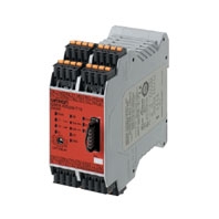
Safety Guard Switching Unit
about this Product Family
Related Contents
last update: January 10, 2013
| Model | G9SX-GS226-T15-[] | G9SX-EX-[] |
|---|---|---|
| Rated supply voltage | 24 VDC | |
| Operating voltage range | -15% to 10% of rated supply voltage | |
| Rated power consumption * | 5 W max. | 2 W max. |
| Model | G9SX-GS226-T15-[] |
|---|---|
| Safety inputs | Operating voltage: 20.4 VDC to 26.4 VDC, Internal impedance: Approx. 2.8 kΩ * |
| Mode selector input | |
| Feedback/reset input |
| Model | G9SX-GS226-T15-[] |
|---|---|
| Instantaneous safety outputs *1
OFF-delayed safety outputs *1 |
P channel MOS-FET outputs
Load current: 0.8 A DC max./output *2 |
| Auxiliary outputs
(for input, output, and error monitoring) |
PNP transistor outputs
Load current: 0.8 A DC max./output *2 |
| External indicator outputs | P channel MOS-FET outputs
Connectable indicators • Incandescent lamp: 24 VDC, 3 to 7 W • LED lamp: 10 to 300 mA DC/output |
| Model | G9SX-EX-[] |
|---|---|
| Rated load | 250 VAC, 3 A/30 VDC, 3 A (resistive load) |
| Rated carry current | 3 A |
| Maximum switching voltage | 250 VAC, 125 VDC |
| Model | G9SX-GS226-T15-[] | G9SX-EX-[] | |
|---|---|---|---|
| Overvoltage category
(IEC/EN 60664-1) |
II | II (Safety relay outputs 13 to 43 and
14 to 44: III) |
|
| Operating time
(OFF to ON state) *1 |
50 ms max. (Safety input: ON) *2
100 ms max. (Logical AND connection input: ON) *3 |
30 ms max. *4 | |
| Response time
(ON to OFF state) *1 |
15 ms max. | 10 ms max. *4 | |
| Allowable switching time for mode
selector input *5 *7 |
450 ms max. | --- | |
| Response time for switching
operating modes *6 *7 |
50 ms max. | --- | |
| ON-state residual voltage | 3.0 V max. for safety outputs, auxiliary outputs, and external indicator outputs | ||
| OFF-state leakage current | 0.1 mA max. for safety outputs and auxiliary outputs, 1 mA max. for external
indicator outputs |
||
| Maximum wiring length of safety
input and logical AND input |
100 m max.
(External connection impedance: 100 Ω max. and 10 nF max.) |
||
| Reset input time
(Reset button pressing time) |
100 ms min. | ||
| Accuracy of OFF-delay time *8 | Within ± 5% of the set value | ||
| Insulation
resistance |
Between logical AND
connection terminals, and power supply input terminals and other input and output terminals connected together |
20 MΩ min. (at 100 VDC) | --- |
| Between all terminals
connected together and DIN track |
100 MΩ min. (at 500 VDC) | ||
| Dielectric
strength |
Between logical AND
connection terminals, and power supply input terminals and other input and output terminals connected together |
500 VAC for 1 min | --- |
| Between all terminals
connected together and DIN track |
1,200 VAC for 1 min | ||
| Between different
poles of outputs |
--- | ||
| Between safety relay
outputs connected together and other terminals connected together |
2,200 VAC for 1 min | ||
| Vibration resistance | Frequency: 10 to 55 to 10 Hz, 0.375-mm single amplitude (0.75-mm double
amplitude) |
||
| Shock
resistance |
Destruction | 300 m/s2 | |
| Malfunction | 100 m/s2 | ||
| Durability | Electrical | --- | 100,000 cycles min.
(rated load, switching frequency: 1,800 cycles/hour) |
| Mechanical | --- | 5,000,000 cycles min.
(switching frequency: 7,200 cycles/ hour) |
|
| Ambient operating temperature | - 10 to 55 °C (with no icing or condensation) | ||
| Ambient operating humidity | 25% to 85% | ||
| Terminal tightening torque *9 | 0.5 Nm | ||
| Weight | Approx. 240 g | Approx. 165 g | |
*7. Only when the G9SX-GS[] is used with manual switching.
*8. This does not include the operating time or response time of internal relays in the G9SX-EX-[].
*9. For the G9SX-[]-RT (with screw terminals) only.
Note: Please see “Ordering Information” below for the actual models that can be ordered.
| Model | G9SX-GS226-T15-[] | G9SX-EX-[] |
|---|---|---|
| Number of Units connected per logical AND output | 4 Units max. | --- |
| Total number of Units connected by logical AND *1 | 20 Units max. | --- |
| Number of Units connected in series by logical AND | 5 Units max. | --- |
| Max. number of Expansion Units connected *2 | --- | 5 Units max. |
| Maximum cable length for logical AND input | 100 m max. | --- |
last update: January 10, 2013