Building Automation
Industrial Automation
Power Automation & Safety


Bangladesh Distributor
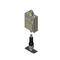
D4C-3002-DK1EJ03
Enclosed Switch
Image
Standard sensitivity, IP67, Snap action, Self-reset mechanism, Single-Pole, Double-Throw type, SPDT, Roller plunger, Oil-resistant cable 3 cores 0.3 m
| Shape/Structure |
General-purpose Limit switches |
|---|---|
| Actuator |
Roller plunger 12 dia. * 5 Sintered stainless steel roller |
| Electrical ratings |
1 A at 30 VDC |
| Contact configuration |
Single-Pole, Double-Throw type |
| Load |
General load |
| Cable specifications |
Oil-resistant cable 3 cores (Cable length: 0.3 m) Diameter: 6 mm dia. |
| Degree of protection |
IEC60529 (JEM): IP67 |
- Ratings / Performance
As of August 8, 2016
| Shape/Structure | General-purpose Limit switches |
|---|---|
| Service life | General type |
| Operating mechanism | Snap action |
| Actuator | Roller plunger 12 dia. * 5 Sintered stainless steel roller |
| Electrical ratings | 1 A at 30 VDC |
| Frequency | 50/60 Hz |
| Leakage current | Approx. 1.7 mA |
| Switching mechanism | Self-reset mechanism |
| Contact configuration | Single-Pole, Double-Throw type |
| Contact form | SPDT |
| Load | General load |
| Ratings (DC): Non-Inductive load | Rated voltage: 30 VDC / Resistive load: 1 A(NC) 1 A(NO) / Lamp load: 1 A(NC) 1 A(NO) |
| Ratings (DC): Inductive load | Rated voltage: 30 VDC / Inductive load: 1 A(NC) 1 A(NO) / Motor load: 1 A(NC) 1 A(NO) |
| Inrush current | NC: 20 A NO: 10 A |
| Protective circuit | Classification of protection against electric shock: Class III Short-circuit protective device: 10 A fuse type gI or gG (IEC269) |
| Indicator | LED (Light when not operating) Voltage: 30 VDC Leakage current: Approx. 1.7 mA |
| Earth terminal | With ground terminal |
| Cable specifications | Oil-resistant cable 3 cores (Cable length: 0.3 m) Diameter: 6 mm dia. |
| Ambient temperature | Operating: -10 to 70 ℃ |
| Ambient humidity | Operating: 35 to 95% |
| Permissible operating speed | 0.1 mm/s to 0.5 m/s |
|---|---|
| Permissible operating frequency (Mechanically) | 120 operations / 1 minute Max. |
| Permissible operating frequency (Electrically) | 30 operations / 1 minute Max. |
| Contact resistance | 150 mOhm Max. (Initial value) * Including the resistance of cable. (Measuring method is contact resistance meter.) |
| Insulation resistance | Between each terminal of the same polarities: 100 MΩ Between live-metallic part and ground: 100 MΩ Between each terminal and non-live-metallic part: 100 MΩ (at 500 VDC Megger Without LED) |
| Dielectric strength | Between each terminal of the same polarities: 1000 V Between live-metallic part and ground: 1500 V Between each terminal and non-live-metallic part: 1500 V (50/60 Hz for 1 min Without LED) |
| Durability (Mechanically) | 10,000,000 operations Min. (No load) (Temperature, Humidity conditions: 5 CEL to 35 CEL, 40 %RH to 70 %RH) |
| Durability (Electrically) | 1,000,000 operations Min. (Resistive load 1 A at 30 VDC) (Temperature, Humidity conditions: 5 CEL to 35 CEL, 40 %RH to 70 %RH) |
| Pollution degree | 3 (EN60947-5-1) |
| Vibration resistance (Malfunction) | Vibration frequency range: 10 to 55 Hz, Double amplitude: 1.5 mm, Contact opening: 1 ms Max. at the free position and the total travel position. |
| Shock resistance (Destruction) | 1,000 m/s2 |
| Shock resistance (Malfunction) | Contact opening is 1 ms Max. at the free position and the total travel position at 500 m/s2. |
| Degree of protection | IEC60529 (JEM): IP67 |
| Mounting specification | Front mounting |
| Operating Force (OF) | Standard value Max. 11.77 N |
|---|---|
| Release Force (RF) | Standard value Min. 4.41 N |
| Pre-Travel (PT) | Standard value 1.8 mm Max. |
| Over-Travel (OT) | Standard value 3 mm Min. |
| Movement Differential (MD) | Standard value 0.2 mm Max. |
| Operating Position (OP) | Standard value 28.5 +/- 1 mm |
As of August 8, 2016
- Mounting holes
As of August 8, 2016

As of August 8, 2016
- Circuits configuration
As of August 8, 2016
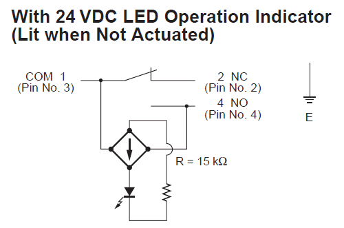
E (ground) is not grounded.
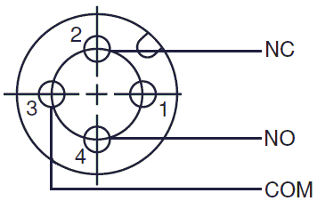
Connector pin arrangement drawing
As of August 8, 2016
- Durability
As of August 8, 2016
Electrical durability curve

As of August 8, 2016

about this Product